Hole
Drill simple, counterbored, countersunk or tapped holes at the points of a sketch, with screw, bolt, dowel and thread sizes.
- Hole HPart workspace toolbar
| SchoolCAD | Onshape | Fusion | SOLIDWORKS |
|---|---|---|---|
| Hole | Hole | Hole | Hole Wizard |
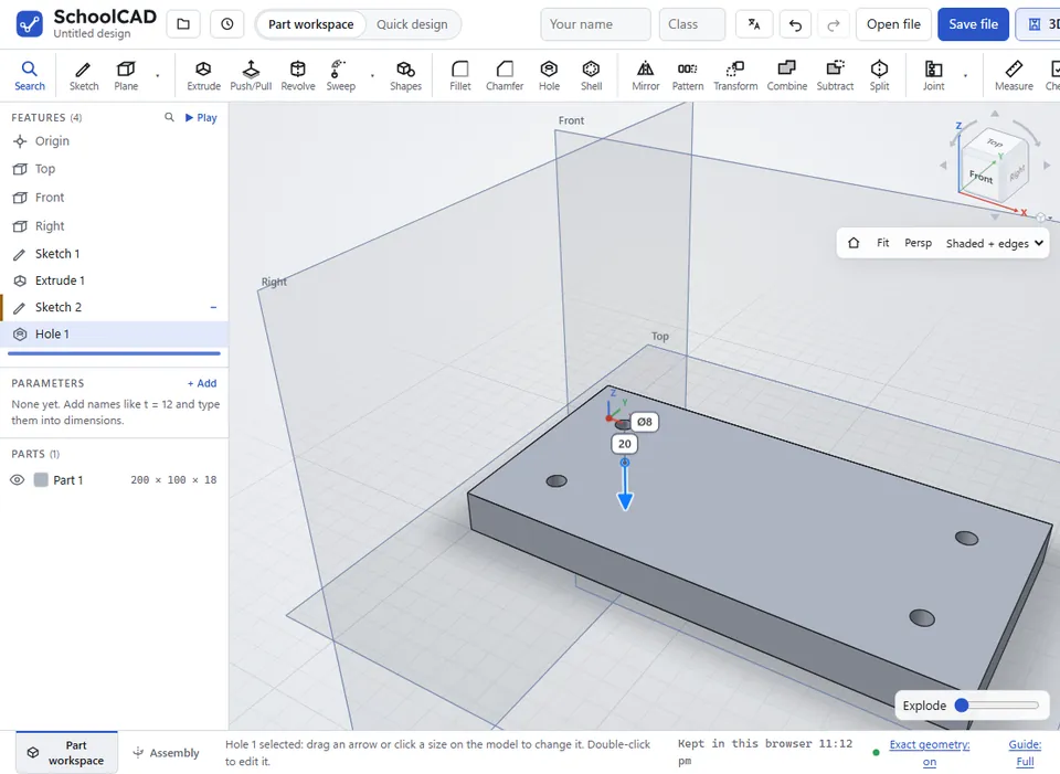
Hole drills real workshop holes into a part: screw holes, bolt holes, dowel holes, cable holes and threaded (tapped) holes. You put a point in a sketch where each hole goes, then pick the size from a list, such as 8g screw, countersunk (4.5 mm) or 8 mm dowel hole, 20 deep. One Hole feature can drill lots of holes at once.
How to use it#
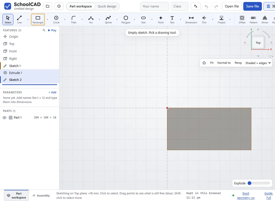
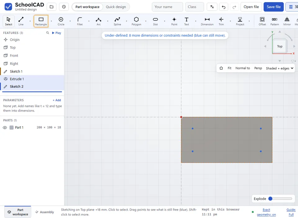
- Start a sketch on the face the holes go into. Use Point (.) to put a point where each hole goes, and add dimensions to put the points in the right place. Finish the sketch.
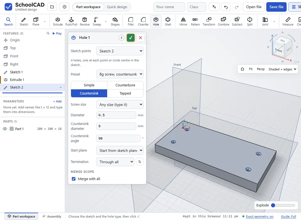
- Click Hole, or press H. The newest sketch with points is chosen for you.
- Choose a Preset, or choose the Hole style. For a screw or bolt to pass through, choose its Screw size and Fit. Or type your own sizes.
- For a Blind hole, drag the arrow at the bottom of the hole, or type the Depth.
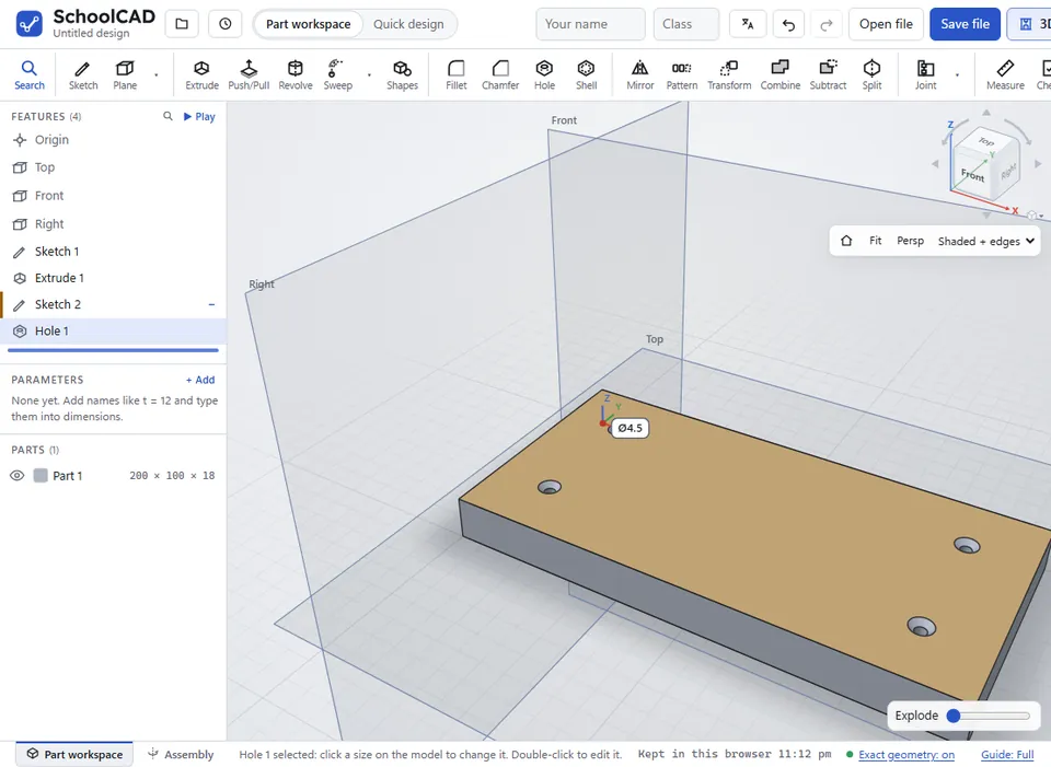
- Check the preview, then click ✓ or press Enter.
Step by step#
Here is the whole thing on screw holes in a shelf, from the SchoolCAD video tutorial.
Options#
| Option | What it does |
|---|---|
| Sketch points | The sketch with the points. It says how many holes it will make. |
| Preset | Workshop sizes for screws, dowels, bolts, a cable hole, shelf pins and tapped holes (M3 to M12). It starts on 8g screw, countersunk (4.5 mm). |
| Hole style | The kind of hole: Simple, Counterbore, Countersink or Tapped. |
| Simple | A plain, straight hole. |
| Counterbore | A wider, flat-bottomed recess for a bolt head. Set the Counterbore diameter and Counterbore depth. |
| Countersink | A cone, so a countersunk screw sits flush. Set the Countersink diameter and the Countersink angle. |
| Tapped | A hole with a screw thread, for a bolt or machine screw (M1.6 to M24). Choose the Size: the hole is drilled at the tap drill size (Tap drill diameter) and the thread goes as deep as the Tapped depth. Normally the thread is cosmetic: it is shown on engineering drawings, as in Onshape and SOLIDWORKS, not modelled as a real spiral. |
| Pitch | Advanced only, for M6 and up: the coarse pitch (the usual one) or a fine pitch (ISO 261), such as M8 × 1. The tap drill changes to suit. |
| Modelled thread (for 3D printing) | Advanced only: the real thread is cut into the hole wall (the ISO 60° profile), so a 3D-printed part takes a real bolt. Leave it off for parts made in the workshop: there the tap cuts the thread. |
| Print fit | With a modelled thread: extra room in the thread, in mm, so a 3D print does not bind on the bolt. 0.1 to 0.3 mm suits most printers. |
| Hand | Advanced only: Right hand (almost every screw) or Left hand (the left pedal of a bike, gas fittings). |
| Screw size | Not for Tapped: a clearance hole for a metric screw or bolt (M3 to M12), the size the screw passes through. With Counterbore, the counterbore fits the screw's head (a socket head cap screw); with Countersink, the countersink fits a countersunk screw. Any size (type it) leaves the sizes to you. Like Size in Onshape's Hole and SOLIDWORKS' Hole Wizard. |
| Fit | With a Screw size: how much room the screw has (ISO 273, as in Onshape and SOLIDWORKS). Close is snug, for parts that must line up exactly; Normal is the usual clearance; Loose is easy to line up, for 3D prints, wood and holes drilled by hand. For M6 they are Ø6.4, Ø6.6 and Ø7. |
| Diameter | The size of the hole, in mm. For Tapped, this is the Tap drill diameter. Type a size of your own and the Screw size goes back to Any size (type it). |
| Start plane | Start from sketch plane measures the depth from the sketch. Start from part measures each hole from where it meets the part, so holes in a curved or sloping face all end up the same depth. |
| Termination | Blind goes as deep as the Depth. Up to next goes through the first wall under each hole, such as the floor of a box but not the shelf below it. Up to face goes down to a flat face you click, and Up to vertex to the level of a corner or a sketch point you click (Onshape: Up to entity · SOLIDWORKS: Up To Surface, Up To Vertex); they follow it if it moves. Through all goes right through. (SOLIDWORKS: End Condition) |
| Depth | Blind only: how deep it goes, in mm. |
| ⇅ (Opposite direction) | The arrow button beside Depth (or beside Termination for Up to next and Through all): drills the other way. |
| Merge scope | Merge with all ticked: it drills every part it meets. Untick it to tick just the parts to drill. |
Tips#
- Change any size and the preset becomes Custom size.
- Choose the Screw size before you change the Hole style: the counterbore or countersink sizes follow the screw. Choose Tapped and the thread Size starts at the same screw size.
- A circle in the sketch works as well as a point: the hole goes at its centre. The size of the circle does not matter, only the Diameter in the dialog.
- Hole finds its own way into the part. If the holes would miss, it tries the other way.
- The arrow only shows for a Blind hole with Start from sketch plane. When you drag it, the steps get smaller as you zoom in. Hold Shift for finer steps, or press Esc to put the depth back.
- Start from part suits curved faces, like the deck of a surf handplane.
- For a row of holes, put several points in one sketch, or make one hole and use Pattern.
- To change a hole later, double-click inside it on the model, or double-click it in the feature tree.
- A modelled thread makes the part much heavier (thousands of triangles), so tick it last, once the design is done. To thread a hole made another way, or a round shaft, use Thread.
If it does not work#
- That face slopes across the holes, so each would need its own depth. With Up to face, every hole goes the same depth, so pick a face square to the holes, or use Start from part.
- That is not in front of the holes. The face or corner is level with the sketch or behind it. Click ⇅.
- First make a sketch on the face and put a Point (or a circle) where each hole goes.
- The sketch has no points or circles to put holes on. Add a point (or a circle) where each hole goes. The end of a line does not count: a hole needs a point of its own, or the centre of a circle.
- The cut did not remove anything. Check the direction, depth or the part it cuts. The points may not be over the part, or the sketch may be on the wrong face.
- The holes miss the part. Put the sketch points over the part (looking along the hole), or flip the direction. This one comes with Start from part.
- The hole is as wide as an M6 thread, so no thread is modelled. A modelled thread needs the hole drilled at the tap drill size: choose the Size again and the Tap drill diameter goes back to it.